Power Supplies
Models of the XT+ Extinguishant Control Panel can include the 5.25 Amp or the 10.25 Amp power supply. 5.25 Amp power supplies are capable of charging batteries with capacities ranging from 7 to 60 Ah. 10.25 Amp power supplies are capable of charging batteries with capacities ranging from 12 to 100 Ah. Both power supplies provide an output voltage of 24V and
A jumper connection for the 5.25 Amp power supply is set at the factory according to input voltage requirements of the customer, either 115 VAC or 230 VAC.
The 10.25 Amp power supply does not provide a jumper connection to select between input voltages. This power supply includes a universal input feature that automatically compensates for input voltages between 95V and 250V AC.
Features
Features of the power supplies include:
DIP Switches
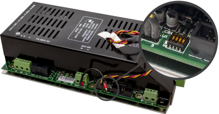
DIP switches are located on the edge of the power supply.
5.25 Amp Power Supply
The following figure illustrates the location of DIP switches on the 5.25 Amp Power Supply:
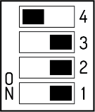
The tables below describe DIP switch settings 1 through 4 of the 5.25 Amp Power Supply. For UL compliance, DIP switches should be set to the defaults, as shown.
SW1&2 together define the Battery Load Test (also known as Battery Impedance Test)
|
|
Switch setting 3 is not used on the 5.25 Amp Power Supply and should be set to OFF.
SW4 defines Battery Manufacturer.
|
Switch 4 |
Description |
|---|---|
|
On (DEFAULT) |
Sets standby batteries for the Powersonic manufacturer. |
|
Off |
Sets standby batteries for the Yuasa manufacturer. |
|
Other manufacturer batteries can be used. Consult the manufacturer's datasheet for proper settings. |
|
10.25 Amp Power Supply
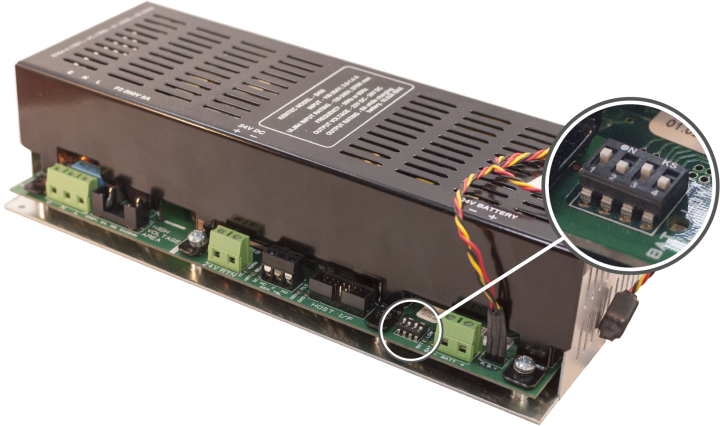
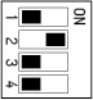
The tables below describes DIP switch settings 1 through 4 of the 10.25 Amp Power Supply.
For UL compliance, DIP Switches 1 and 2 must be set to the default, as shown.
|
|
||||||||||||||||||||||||
- Disabling Battery Indication - Set DIP switch 1 to the ON position, DIP switch 3 to the ON position and DIP switch 4 to the OFF position to disable the "BATTERY DISCONNECTED" warning indication.
- Disabling the Impedance Test - Set DIP switch 1 to the ON position and DIP switch 3 to the OFF position to disable the battery impedance test and trouble reporting.
Special Application Mode Table
|
SW1 |
SW2 |
SW3 |
SW4 |
Battery Mfr. |
Battery Size |
Ground Trouble |
Impedance Test |
Battery Missing Trouble |
|---|---|---|---|---|---|---|---|---|
|
ON |
ON |
ON |
ON |
RESERVED FOR FUTURE USE |
||||
|
ON |
ON |
OFF |
ON |
PowerSonic |
> 18 Ah |
Static |
Disabled |
Reported |
|
ON |
ON |
ON |
OFF |
Yuasa |
< 18 Ah |
Static |
1 min |
Masked |
|
ON |
ON |
OFF |
OFF |
Yuasa |
> 18 Ah |
Static |
Disabled |
Reported |
Light shading of the table indicates "production" or "demo" use.
Dark shading of the table indicates a "normal, but impedance test disabled" use.
Status Indicators
|
LED Indicator |
Condition |
|---|---|
|
The AC power is connected. |
|
| EARTH FLT |
The 24V DC supply is connected to the ground. |
|
An
internal fault has been detected in the power
supply module. The HEARTBEAT indicator
blinks different patterns to indicate the fault.
|
|
|
The unit is operating from battery and the battery voltage is below 21 V OR The unit is operating from AC power and the battery voltage is below 24 V. |
|
| BATTERY LOW and CHARGER FAULT | The battery impedance exceeds the acceptable limit. Install new batteries. |
|
BATTERY DISCON |
Standby batteries are disconnected. |
|
HEARTBEAT |
The power supply is functioning. |
|
The 24V DC supply is supplying power to the load. |